- 浏览: 809968 次
-

文章分类
最新评论
-
469957559:
能受累发个源码包吗 我弄了好几天 没出来 想学习下 469 ...
SWFUpload多文件上传 文件个数限制 setStats() -
flywing521:
为什么配置 web.xml 时报错?
flex实现session -
宅男贰号:
iteye我不常上,回复时请发件通知一下,wooh@163.c ...
flex实现session -
宅男贰号:
ThreadLocal不是线程,可以理解为它是线程变量,你的例 ...
flex实现session -
jstl1point0:
学习了,监听后oncreate和onresum也不会执行了是吧 ...
Android横竖屏的设置和使用
Writing a Simple USB Driver
Since this column began, it has discussed how a Linux driver writer can create various types of kernel drivers, by explaining the different kernel driver interfaces including TTY, serial, I2C and the driver core. It is time to move on now and focus on writing real drivers for real hardware. We start by explaining how to determine what kind of kernel driver interface to use, tricks to help figure out how the hardware actually works and a lot of other real-world knowledge.
Let's begin with a goal of making a simple USB lamp device work well with Linux. Editor Don Marti pointed out a neat device, the USB Visual Signal Indicator, manufactured by Delcom Engineering and shown in Figure 1. I have no relationship with this company; I just think they make nice products. This device can be ordered on-line from the Delcom Web site,www.delcom-eng.com. Don challenged me to get the device working on Linux, and this article explains how I did it.
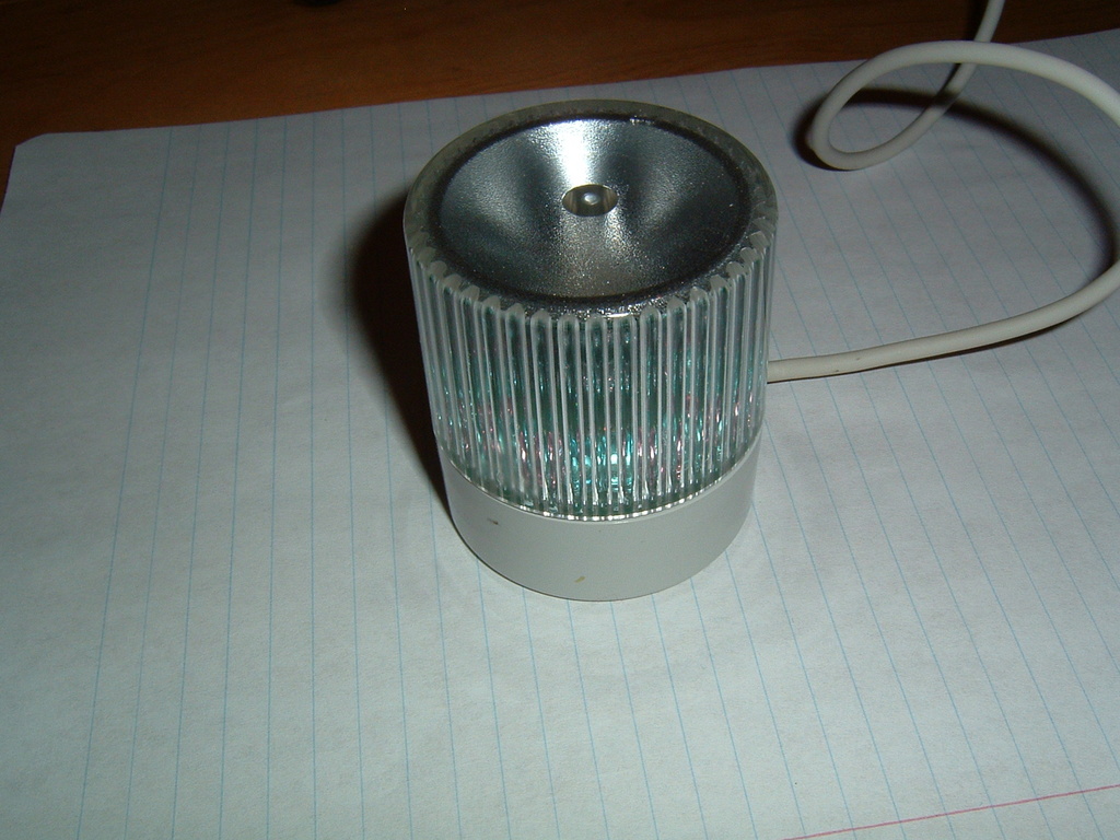
Figure 1. Delcom's USB Visual Signal Indicator is a simple first USB programming project.
The first goal in trying to write a driver for a device is to determine how to control the device. Delcom Engineering is nice enough to ship the entire USB protocol specification their devices use with the product, and it also is available on-line for free. This documentation shows what commands the USB controller chip accepts and how to use them. They also provide a Microsoft Windows DLL to help users of other operating systems write code to control the device.
The documentation for this device is only the documentation for the USB controller in the lamp. It does not explicitly say how to turn on the different color LEDs. For this, we have to do a bit of research.
No Docs? Reverse Engineer It!
If the USB protocol for this device had not been documented or available to me, I would have had to reverse engineer this information from the device itself. A handy tool for this kind of work is a free program called USB Snoopy,www.wingmanteam.com/usbsnoopy; another version of it is SnoopyPro,usbsnoop.sourceforge.net. These programs are both Windows programs that allow users to capture the USB data that is sent to and received from any USB device on a Windows system. All a developer needs to do is find a Windows machine, install the Windows driver provided by the manufacturer for the device and run the snoop program. The data is captured to a file to be analyzed later. Perl scripts can help filter some of the extra noise in the output of these snoop programs into an easier format to understand.
Another method a few people have used to reverse engineer the USB protocol of a device is to run a Windows instance using VMware on top of Linux. VMware enables the Windows instance to talk to all of the USB devices plugged in to the Linux machine by sending data to Linux though the usbfs. A simple modification to the usbfs causes all data flowing though it to be logged to the kernel log. Using this, the full USB traffic stream can be captured and later analyzed.
After opening up the lamp device, making sure not to lose the spring that easily pops out when unscrewing the device, the circuit board can be inspected (Figure 2). Using an ohmmeter, or any kind of device for detecting a closed circuit, it was determined that the three different LEDs are connected to the first three pins of port 1 on the main controller chip.
In reading the documentation, the USB command to control the levels of the port 1 pins isMajor 10, Minor 2, Length 0. The command writes the least significant byte of the USB command packet to port 1, and port 1 is defaulted high after reset. So, that is the USB command we need to send to the device to change the different LEDs.
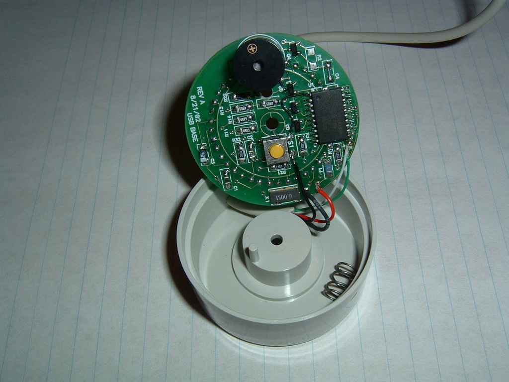
Figure 2. The three LEDs are connected to the first three pins of the controller chip.
Now that we know the command to enable a port pin, we need to determine which LED color is connected to which pin. This is easy to do with a simple program that runs through all possible combinations of different values for the three port pins and then sends the value to the device. This program enabled me to create a table of values and LED colors (Table 1).
Table 1. Port Values and the Resulting LED Patterns
| 0x00 | 000 | Red, Green, Blue |
| 0x01 | 001 | Red, Blue |
| 0x02 | 010 | Green, Blue |
| 0x03 | 011 | Blue |
| 0x04 | 100 | Red, Green |
| 0x05 | 101 | Red |
| 0x06 | 110 | Green |
| 0x07 | 111 | No LEDs on |
So, if all pins on the port are enabled (a value of 0x07 hex), no LEDs are on. This matches up with the note in the data sheet that stated, “Port 1 is defaulted high after reset.” It would make sense not to have any LEDs enabled when the device is first plugged in. This means we need to turn port pins low (off) in order to turn on the LED for that pin. Using the table, we can determine that the blue LED is controlled by pin 2, the red LED by pin 1 and the green LED by pin 0.
Armed with our new-found information, we set off to whip up a quick kernel driver. It should be a USB driver, but what kind of interface to user space should we use? A block device does not make sense, as this device does not need to store filesystem data, but a character device would work. If we use a character device driver, however, a major and minor number needs to be reserved for it. And how many minor numbers would we need for this driver? What if someone wanted to plug 100 different USB lamp devices in to this system? To anticipate this, we would need to reserve at least 100 minor numbers, which would be a total waste if all anyone ever used was one device at a time. If we make a character driver, we also would need to invent some way to tell the driver to turn on and off the different colors individually. Traditionally, that could be done using different ioctl commands on the character driver, but we know much better than ever to create a new ioctl command in the kernel.
As all USB devices show up in their own directory in the sysfs tree, so why not use sysfs and create three files in the USB device directory, blue, red and green? This would allow any user-space program, be it a C program or a shell script, to change the colors on our LED device. This also would keep us from having to write a character driver and beg for a chunk of minor numbers for our device.
To start out our USB driver, we need to provide the USB subsystem with five things:
-
A pointer to the module owner of this driver: this allows the USB core to control the module reference count of the driver properly.
-
The name of the USB driver.
-
A list of the USB IDs this driver should provide: this table is used by the USB core to determine which driver should be matched up to which device; the hot-plug user-space scripts use it to load that driver automatically when a device is plugged in to the system.
-
A probe() function called by the USB core when a device is found that matches the USB ID table.
-
A disconnect() function called when the device is removed from the system.
The driver retrieves this information with the following bit of code:
static struct usb_driver led_driver = {
	.owner =	THIS_MODULE,
	.name =		"usbled",
	.probe =	led_probe,
	.disconnect =	led_disconnect,
	.id_table =	id_table,
};
The id_table variable is defined as:
static struct usb_device_id id_table [] = {
	{ USB_DEVICE(VENDOR_ID, PRODUCT_ID) },
	{ },
};
MODULE_DEVICE_TABLE (usb, id_table);
The led_probe() and led_disconnect() functions are described later.
When the driver module is loaded, this led_driver structure must be registered with the USB core. This is accomplished with a single call to the usb_register() function:
retval = usb_register(&led_driver);
if (retval)
        err("usb_register failed. "
            "Error number %d", retval);
Likewise, when the driver is unloaded from the system, it must unregister itself from the USB core:
usb_deregister(&led_driver);
The led_probe() function is called when the USB core has found our USB lamp device. All it needs to do is initialize the device and create the three sysfs files, in the proper location. This is done with the following code:
/* Initialize our local device structure */
dev = kmalloc(sizeof(struct usb_led), GFP_KERNEL);
memset (dev, 0x00, sizeof (*dev));

dev->udev = usb_get_dev(udev);
usb_set_intfdata (interface, dev);

/* Create our three sysfs files in the USB
* device directory */
device_create_file(&interface->dev, &dev_attr_blue);
device_create_file(&interface->dev, &dev_attr_red);
device_create_file(&interface->dev, &dev_attr_green);

dev_info(&interface->dev,
    "USB LED device now attached\n");
return 0;
The led_disconnect() function is equally as simple, as we need only to free our allocated memory and remove the sysfs files:
dev = usb_get_intfdata (interface);
usb_set_intfdata (interface, NULL);

device_remove_file(&interface->dev, &dev_attr_blue);
device_remove_file(&interface->dev, &dev_attr_red);
device_remove_file(&interface->dev, &dev_attr_green);

usb_put_dev(dev->udev);
kfree(dev);

dev_info(&interface->dev,
         "USB LED now disconnected\n");
When the sysfs files are read from, we want to show the current value of that LED; when it is written to, we want to set that specific LED. To do this, the following macro creates two functions for each color LED and declares a sysfs device attribute file:
#define show_set(value)	                           \
static ssize_t                                     \
show_##value(struct device *dev, char *buf)        \
{                                                  \
   struct usb_interface *intf =                    \
      to_usb_interface(dev);                       \
   struct usb_led *led = usb_get_intfdata(intf);   \
                                                   \
   return sprintf(buf, "%d\n", led->value);        \
}                                                  \
                                                   \
static ssize_t                                     \
set_##value(struct device *dev, const char *buf,   \
            size_t count)                          \
{                                                  \
   struct usb_interface *intf =                    \
      to_usb_interface(dev);                       \
   struct usb_led *led = usb_get_intfdata(intf);   \
   int temp = simple_strtoul(buf, NULL, 10);       \
                                                   \
   led->value = temp;                              \
   change_color(led);                              \
   return count;                                   \
}                                                  \

static DEVICE_ATTR(value, S_IWUGO | S_IRUGO,
                   show_##value, set_##value);
show_set(blue);
show_set(red);
show_set(green);
This creates six functions, show_blue(), set_blue(), show_red(), set_red(), show_green() and set_green(); and three attribute structures, dev_attr_blue, dev_attr_red and dev_attr_green. Due to the simple nature of the sysfs file callbacks and the fact that we need to do the same thing for every different value (blue, red and green), a macro was used to reduce typing. This is a common occurrence for sysfs file functions; an example of this in the kernel source tree is the I2C chip drivers in drivers/i2c/chips.
So, to enable the red LED, a user writes a 1 to the red file in sysfs, which calls the set_red() function in the driver, which calls the change_color() function. The change_color() function looks like:
#define BLUE	0x04
#define RED	0x02
#define GREEN	0x01
   buffer = kmalloc(8, GFP_KERNEL);

   color = 0x07;
   if (led->blue)
      color &= ~(BLUE);
   if (led->red)
      color &= ~(RED);
   if (led->green)
      color &= ~(GREEN);
   retval =
      usb_control_msg(led->udev,
                      usb_sndctrlpipe(led->udev, 0),
                      0x12,
                      0xc8,
                      (0x02 * 0x100) + 0x0a,
                      (0x00 * 0x100) + color,
                      buffer,
                      8,
                      2 * HZ);
   kfree(buffer);
This function starts out by setting all bits in the variable color to 1. Then, if any LEDs are to be enabled, it turns off only that specific bit. We then send a USB control message to the device to write that color value to the device.
It first seems odd that the tiny buffer variable, which is only 8-bytes long, is created with a call to kmalloc. Why not simply declare it on the stack and skip the overhead of dynamically allocating and then destroying it? This is done because some architectures that run Linux cannot send USB data created on the kernel stack, so all data that is to be sent to a USB device must be created dynamically.
With this kernel driver created, built and loaded, when the USB lamp device is plugged in, the driver is bound to it. All USB devices bound to this driver can be found in the sysfs directory for the driver:
$ tree /sys/bus/usb/drivers/usbled/
/sys/bus/usb/drivers/usbled/
`-- 4-1.4:1.0 ->
../../../../devices/pci0000:00/0000:00:0d.0/usb4/4-1/4-1.4/4-1.4:1.0
The file in that directory is a symlink back to the real location in the sysfs tree for that USB device. If we look into that directory we can see the files the driver has created for the LEDs:
$ tree /sys/bus/usb/drivers/usbled/4-1.4:1.0/
/sys/bus/usb/drivers/usbled/4-1.4:1.0/
|-- bAlternateSetting
|-- bInterfaceClass
|-- bInterfaceNumber
|-- bInterfaceProtocol
|-- bInterfaceSubClass
|-- bNumEndpoints
|-- blue
|-- detach_state
|-- green
|-- iInterface
|-- power
|   `-- state
`-- red
Then, by writing either 0 or 1 to the blue, green and red files in that directory, the LEDs change color:
$ cd /sys/bus/usb/drivers/usbled/4-1.4:1.0/
$ cat green red blue
0
0
0
$ echo 1 > red
[greg@duel 4-1.4:1.0]$ echo 1 > blue
[greg@duel 4-1.4:1.0]$ cat green red blue
0
1
1
Now that we have created a simple kernel driver for this device, which can be seen in the 2.6 kernel tree at drivers/usb/misc/usbled.c or on theLinux JournalFTP site at (ftp.linuxjournal.com/pub/lj/listings/issue120/7353.tgz), is this really the best way to talk to the device? What about using something like usbfs or libusb to control the device from user space without any special device drivers? In my next column, I will show how to do this and provide some shell scripts to control the USB lamp devices plugged in to the system easily.
If you would like to see kernel drivers written for any other types of devices, within reason—I'm not going to try to write an NVIDIA video card driver from scratch—please let me know.
Thanks to Don Marti for bugging me to get this device working on Linux. Without his prodding it would have never gotten finished.
Greg Kroah-Hartman currently is the Linux kernel maintainer for a variety of different driver subsystems. He works for IBM, doing Linux kernel-related things, and can be reached atgreg@kroah.com.


发表评论

相关推荐
This is a document to develop the windows usb driver woth wdf
Usb Driver Programming (2) - Writing Your Own Device Driver (2002 Elektor Electronica Excerpt).pdf
Writing a Device Driver for Video-Capture Devices
writing-an-alsa-driver
Writing A Compiler In Go Writing A Compiler In Go Writing A Compiler In Go
writing-a-simple-operating-system-from-scratch从零开始写一个简单的操作系统该代码是我在学习Nick Blundel的PDF教程时按照教程编写的,分享出来,供OS爱好者参考。原,作者:英国伯明翰大学计算机学院教师 Nick ...
如何编写一个简单的ALSA驱动,配有实例。让ALSA不再神秘。
Guidelines for Writing a Scientific Paper(英文版)
Academic Writing: A Handbook for International Students
Writing a Good Resume.pptWriting a Good Resume.ppt
If you do decide to go for a custom driver, Cant's simple generic drivers will help get you started.) The second strength of this book is its discussion of a variety of techniques for testing and ...
linux alsa driver相关,介绍的很详细
An Overview on Writing a VHDL Testbench
A tutorial on writing a shell extension that adds pages to the properties dialog of files.(17KB)
Writing Network Device Drivers
Writing Windows WDM Device Drivers 英文版 djvu
So, we started writing our own encoder. It turned out to be very complex and difficult. The one we wrote from scratch was really-really slow.. some functions had fourth order complexity (mostly the ...
On Writing_ A Memoir of the Craft - Stephen King.mobi On Writing_ A Memoir of the Craft - Stephen King.mobi On Writing_ A Memoir of the Craft - Stephen King.mobi On Writing_ A Memoir of the Craft...